There are three types of magnetizing roasters: shaft furnace, rotary kiln and boiling furnace. The 70 m 3 shaft furnace is extended from the original 0.45 m to 1.044 m with the same dimensions of the 50 m 3 shaft furnace. Meanwhile, in a row of six additional heating belt detonating disposed transverse beams; five additional manifold strip in a preheating portion; four additional coal gas discharge column in the reduction zone. In this way, since the exhaust gas, the heated gas, the reduced gas, and the like are uniformly distributed in the furnace, the furnace condition is improved, the volume is increased, the throughput is increased, and the heat consumption is reduced. The structure of the furnace body is shown in Figure 3. The 100 m 3 shaft furnace is doubled and the volume is expanded to 100 m 3 in the case where the cross section of the 50 m 3 shaft furnace is constant. In this way, the processing capacity of the ore is also doubled accordingly.
Welded Mesh Fence,Welded Wire Mesh Fence,Bending Welded Mesh Fence,Welded Wire Mesh Fence Panels Hebei Qianye Metal Product Co., Ltd. , https://www.qymsteelfence.com
(1) The shaft furnace shaft furnace is mainly a furnace type for treating lump ore. The large-scale industrial magnetization roasting using the shaft furnace was built in Anshan, China in 1926, so it is called “Anshan-type shaft furnaceâ€. China's scientific research, design and The production department has continuously improved the structure and auxiliary equipment of the furnace in many years of research, design and production practice. Large improvements into the shaft furnace 70, 100 and 160 m 3 in volume based on the original volume of 50 m 3 Anshan the shaft furnace. The ore processing capacity is increased from 6 to 10 tons per unit hour to 30 to 40 tons per unit hour. At present, there are more than 100 types of shaft furnaces in China for production.
The shaft furnace is composed of four parts: the feeding system in the upper part of the furnace top, the furnace body, the discharging system in the lower part of the furnace body and the smoking system. The inside of the furnace body is divided into three parts: pre-tropical zone, heating zone and reduction zone from top to bottom. From the cross-section, the upper part of the furnace is wider, gradually shrinks downward, and gradually expands to the widest part of the reduction belt after the narrowest part of the heating belt (the waist of the furnace). The residence time of the ore in the furnace is 6 to 10 hours.
The effective volume of the 50 m 3 shaft furnace is 50 m 3 , and the shape of the furnace body is 66 m long, 5.3 m wide and 9.7 m high. The narrowest width of the heating belt is 0.45 meters. The widest width of the reduction belt is 1.76 meters. The structure of the furnace body and the sectional arrangement are shown in Figures 1 and 2. 
 [next]

160 m 3 shaft furnace in the case of 70 m 3 shaft furnace constant cross-sectional size of the furnace has doubled, to expand the volume of 160 m 3. Its ore processing capacity (design) is 30 to 40 tons per unit hour.
The auxiliary equipment for the shaft furnace mainly has a roller type ore discharge machine installed on both sides of the lower part of the reduction belt of the furnace body. It is installed along the length of the furnace body. One set of each side of the 50 m 3 and 70 m 3 shaft furnace; 100 m Two sets of 3 and 160 m 3 shaft furnaces are installed on each side. The discharge roller of the roller concentrator is used to discharge the calcined ore. The center line is immersed in the water seal pool, and the rotation speed can be adjusted according to the ore reduction quality to control the technical performance of the discharge roller type discharge machine.
The lower part of the discharge roller has a carry-out machine for carrying out the roasting ore. The calcined ore is quenched by the discharge roller and then falls on the unloading machine and transported out by the unloading machine.
The top of the shaft of the shaft furnace is the feeding funnel, the sides of the funnel are exhaust pipes, the corresponding exhaust pipe is connected with the exhaust pipe, and two dust collectors are installed to form two sets of smoke exhausting systems, and the smoke of the two sets of dust collectors. After the gas is passed through the cyclone, the exhaust gas is discharged into the atmosphere by an exhaust fan.
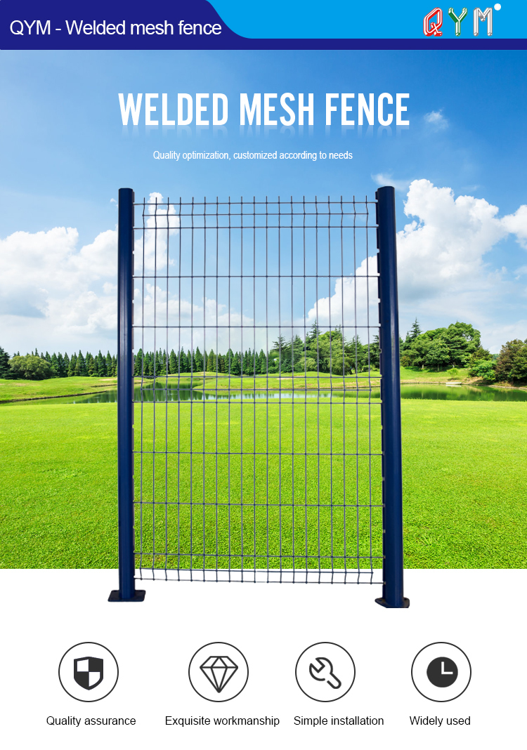
QYM-Welded mesh fence
It is an economical version of the panel system, constructed from a welded mesh panel with longitudinal profiles that forms arigid fence. The fence panel is welded with high quality low carbon steel wire, surface treated by electrostatic polyester powder spray coating over galvanized materials, then connected with post by suitable clips. Due to its simple structure, easy installation, nice appearance, more and more customers regard welded mesh fence as the preferred common protective fence.
