As advanced ceramic material's extraordinary electrical insulation, thermal characteristics, physical properties in comparison with tradditional metal, glass and plastic material. These make structural ceramic components is widely used in electrical & electronic devices,petrochemical industry, machinery, intergrated semiconductors manufacturing, aerospace in a varity of fields. They work as support component, connection part, terminal insulator, ceramic body, ceramic shell ,heat-sink, engineering tools and so on. Structural Ceramic Component,High Precision Structural Ceramic Component,Zirconia Ceramic Structural Component,Structural Component Ceramic Part Type,Structural Ceramics Jinghui Industry Ltd. , https://www.ceramicteks.com
Our factory has been dedicating to a wide range of technical structural ceramic components, including alumina ceramic parts, zirconia ceramic parts, silicon nitride ceramic parts, aluminum nitride ceramic parts, boron nitride ceramic parts. They are usually shaped by dry pressed, hot pressed, ceramic injection molding, isostatic pressed, then cured under high temperature to obtain the dense ceramic body.
In the high-end manufacturing industries, the precision dimensions is needed to reach the fitting relationship. In order to meet the requirement, we set up the CNC, fine grinding workshop to achieve the toughest challenge from our customers. Moreover, the surface finishs is needed to raise or increase the specific fuction in the application, such as the polished surface will reduce the friction, the glazed surface will increase the insulation strength, a metallizes surface will realize the bonding relationship from ceramics to metals, you could find the solutions here for the special requests with our comprehensive production equipment.
Live cable identification instrument field identification cable diagram
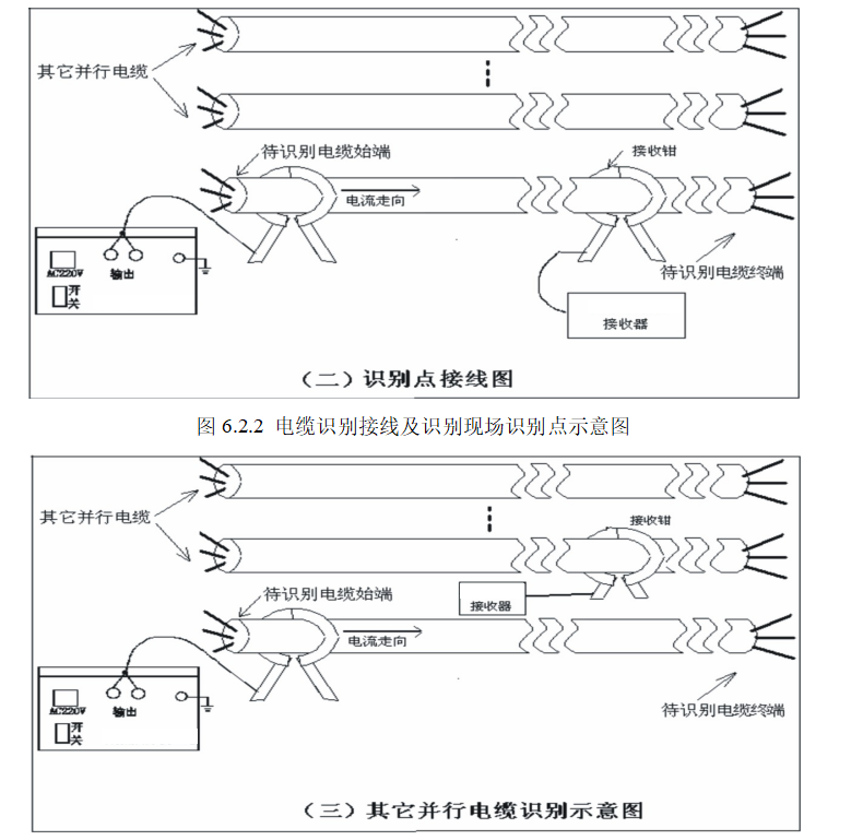
Field identification
If it is the open control site, each cable is clamped with the receiving clamp. Only the signaled cable (the identified cable) should have the head pointer positively biased and the maximum amplitude, and the main cable can only be reverse biased and amplitude. small.
Note: The transmitting clamp and the receiving clamp cannot change direction arbitrarily. All cables must be kept in one direction. Otherwise, the most powerful criterion cannot be used according to the direction.
Figure 6.2.2 Cable identification wiring and identification of site identification points
Figure 6.2.3 Cable identification wiring and identification of other parallel cables on site
7. Identification of power outage cable
This instrument is mainly used for the identification of live cables. Of course, it can also be used for the identification of power-off cables. It has the advantages of not changing the cable wiring, adapting to the large resistance range of the cable grounding loop and strong anti-interference.
This instrument can be used for two types of wiring when it is used for power cable identification.
7.1 Identify the exact same wiring and method of operation with live cables
See Figure 6.2.1 and Figure 6.2.2
7.2 Wiring method without output coupling clamp
This wiring is wired to the traditional identifier
Figure 7.1.2 Recommended power cable and waveform diagram for power failure cable without output coupling clamp
The calibration identification and field identification methods of the receiver are as described in 6.2.1 and 6.2.2.
When the output coupling clamp is not used, the wiring is as shown in Figure 7.1.2. The shield is not used because the shield is not completely connected, or the outer sheath of the cable is damaged, and the multi-point grounding of the cable shield affects the accuracy of the identifier.
8, the handling of special circumstances
8.1 Cable copper shield is stolen, but I do not know where to find and identify
When there is a break point in the middle of the copper shield of the cable to be identified, the instrument is not used for live identification, because the coupling method cannot add the identification signal. This situation can be handled as follows:
8.1.1 Know the beginning of the live cable and judge whether there is a break point in the middle of the copper shield of the cable:
The live cable identification instrument can be used to couple and add signals at the beginning of the live cable to be judged. The live cable identification instrument is clamped and detected from the signal source by about 3m. If the effective signal is not detected, the copper shielding layer of the cable has a disconnection point.
8.1.2 Know the beginning of the cable to find the location of the cable copper shield break point
The cable must be powered off. After the power failure, the cable fault tester can be used. The low-voltage pulse method is used to measure the position of the shield break point as shown below.