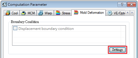
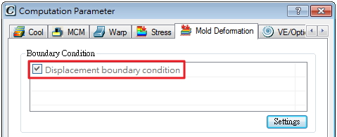
Generally speaking, there are two common factors that cause mold insert deformation in the general molding process.  One happens when the melt forces forward into the cavity under high mechanical screw force during the filling and packing stage. In general, the driven pressure over 200 MPa will induce deformation on mold-insert (as ejector, lifter and actions). The other cause is the unbalanced temperature distribution, which results in different thermal expansion/shrinkage within the mold components. Mold deformation not only can potentially impact the mold life cycle, but also influence the dimensional precision of the final products, In order to tackle this problem head-on, Moldex3D supports its users to better evaluate the mold deformation issue by providing the detailed stress and displacement analyses on  mold-basecomponents  under different molding conditions. Furthermore, using Moldex3D for design and process revision, users can also optimize the molding conditions and build a better mold to further reduce the displacement amount. For Mold Deformation, Moldex3D users can create all the mold components in a numerical model and run an accurate analysis, considering the influences of each mold part. Moldex3D’s Stress Module can accurately simulate various molding scenarios under different user-defined molding conditions and mold designs with two important parameters, the cavity pressure during the filling stage and the mold temperature distribution after the cooling period taking into consideration. Step 1. Launch Moldex3D Project and import the prepared model with mold-inserts. Step 2. Open the Computation Parameter and click the Mold Deformation tab. Click Settings to call Moldex3D Designer interface for the setting of boundary conditions. An appropriate setting of boundary conditions is very pivotal to get an accurate analysis of mold deformation. Step 3. In the Mold Deformation BC setting interface, user can set displacement condition on the nodes. Click Step 4. The t nodes are set fixed (0 mm displacement) by default, but users can edit or re-assign the condition anytime by clicking the existing item. Or click on the Arrow ( Step 5. Back to Computation Parameter, the item Displacement boundary condition under Mold Deformation tab will be checked, meaning there is BC assigned to the model. Click OK to confirm the setting and finish other settings of analysis project in New Run Wizard. Step 6. To run the Mold Deformation analysis, click Analysis Step 7. Mold Deformation analysis results: Von Mises stress is a scalar stress value that can be calculated from stress tensor. It can be used to evaluate whether a ductile material will start yielding when it suffers some external force or stress. The material will deform plastically once the von Mises stress locally reaches yield strength. Double Filter Oil,Oil Filtering Machine,Centrifugal Oil Filter,Oil Press Mianyang Xinyu Agricultural Machinery Manufacturing Co. , https://www.xyoilpress.com
Note: To run a Mold Deformation analysis will require an Add-on license of Moldex3D Stress Module)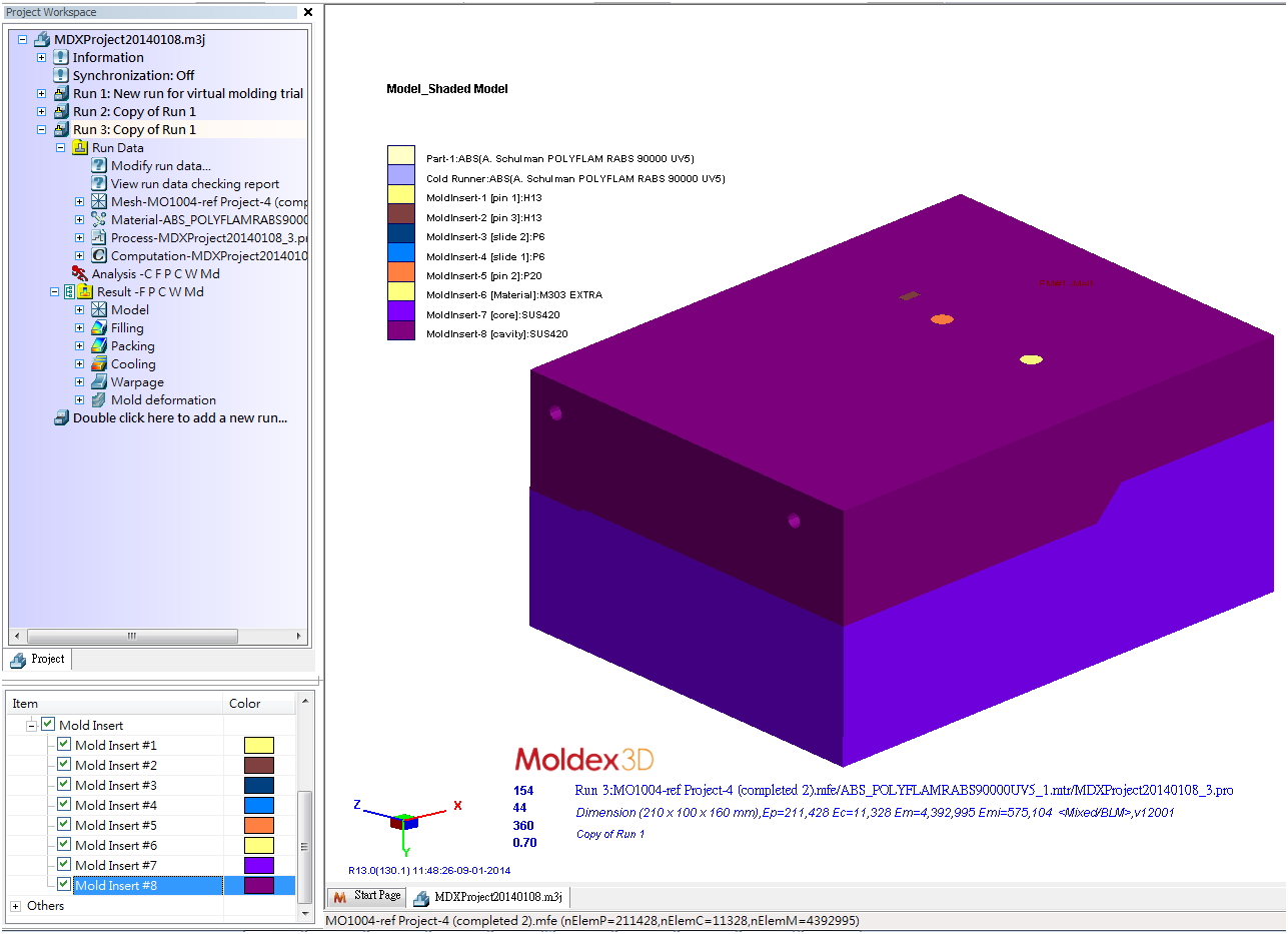
![]() Â to create a new constrain BC, select nodes (will be in yellow) to apply, and click
 to create a new constrain BC, select nodes (will be in yellow) to apply, and click ![]()  to confirm the selection. Then, specify the condition information: name and displacement in x, y, z directions.
 to confirm the selection. Then, specify the condition information: name and displacement in x, y, z directions.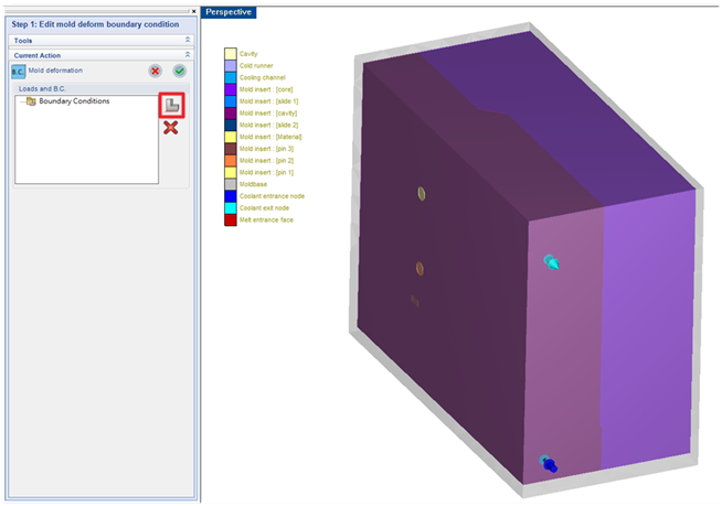 The Mold Deformation Boundary Condition setting interface
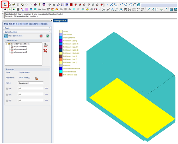
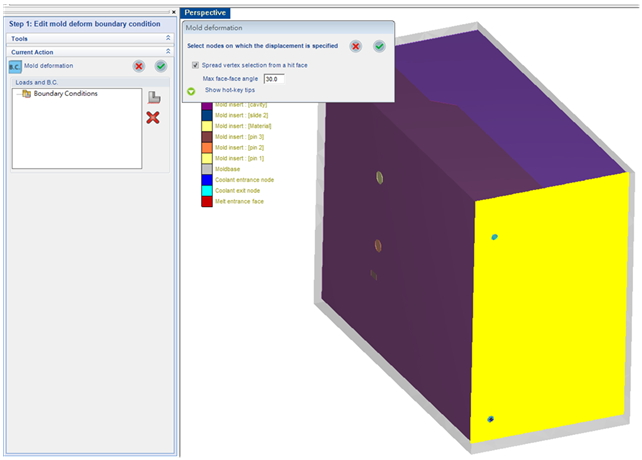 Nodes applied with constrained boundary will be marked yellow
![]() ) button to re-define the selected nodes . After that, users may click
) button to re-define the selected nodes . After that, users may click ![]() Â to complete the setting.
 to complete the setting.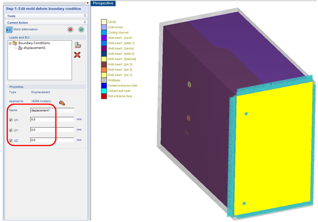
![]()  inproject workspace, add Mold deformation –Mdinto Analysis sequence and click Run Now.
 inproject workspace, add Mold deformation –Mdinto Analysis sequence and click Run Now.
Total Displacement result illustrates how each insert components deformed, which can directly impact the dimensional quality of the molding product.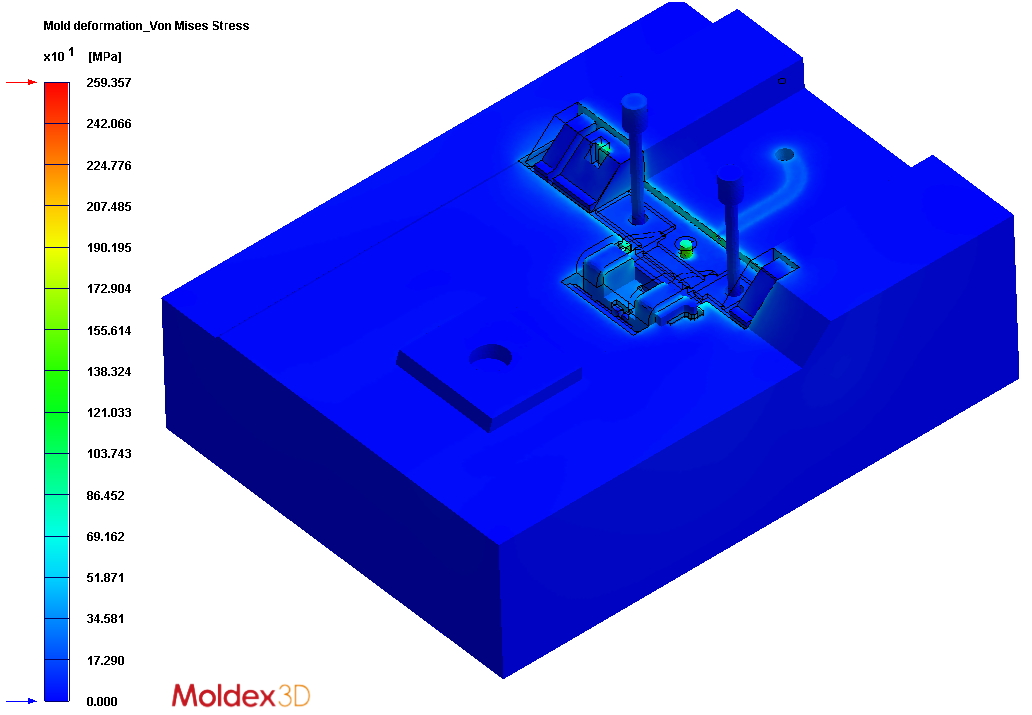 Von Mises Stress
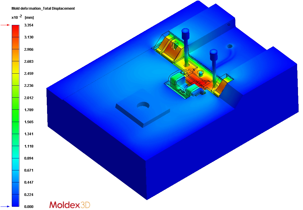 Total Displacement