Balanced melt flow is the key to successful multi-cavity medical molds- to maximize the quality and reduce the quality variation of medical devices. Polymer melt is a complex fluid and its viscosity is sensitive to shear rate and temperature. Since the melt temperature inside the runner is hardly uniform, especially for the multi-cavity mold, it is difficult to achieve flow balance between cavities. Moreover, the effective packing time and the cooling time of multi-cavity molds are all different. This will easily lead to variations in part size, weight, and even functions. See Figure 1 as an example of an unbalanced filling as the melt enters the sub-runner. Runner balancing in multi-cavity molds improves the chance that all cavities will fill and pack at the same time. Runner balancing is highly recommended for multi-cavity molds and bringing more cavities into the mold can benefit productivity. While doing so, it is even more important to ensure part consistency among the cavities because a large part weight or dimension variation means reject and loss. Aside from occurring in the mold with poor vent or runner layout, flow imbalance may also occur in the mold with geometrically-balanced runners. It is not uncommon to see flow imbalance even in a simple 8-cavity mold. Since it’s no stranger to molders, many methods have been developed to bring balance back to the flow. They can be grouped as timing control and melt quality control. How do they work? We must first understand the origin of unbalanced filling. Unbalanced filling is caused by non-uniform melt temperature distribution as the melt turns and diverges in the runner system. Figure 2 shows the shear rate profile which is higher close to the wall and lower near the center. Higher shear rate leads to more friction thus causing the so called “viscous heating†or “shear heating†if the accumulated heat cannot dissipate through the mold fast enough. We often see a 20 some degrees Celcius melt temperature increase when there is significant viscous heating. The primary runner in Figure 3 is an example and note that as the melt splits into two flows, the temperature profile is no longer symmetric and hotter on the inside and colder on the outside. Melt thus travels faster on the inside due to higher temperature and this causes flow imbalance after another split. This phenomenon can be very obvious for materials with a strong viscosity-temperature dependency such as PMMA. Knowing that the hotter melt may reach the cavity earlier, one can design a longer runner or move the split location to compensate for the difference of travel time. However, it requires lots of guessing and mold fixes. And if there is a change of material or processing condition, the required fixing will be different accordingly. Another timing control method is to use valve-gate control to ensure the melt enters the cavity at the same time. Although the adjustment can be flexible, it requires more investment and more frequent maintenance. With the help of filling simulation using Moldex3D, either the extent of runner adjustment or the valve on/off control can be determined much earlier during the mold design stage. Although the previous methods could balance the flow, the temperature distributions among cavities still vary which could lead to different part shrinkage ratio. Luckily there is this second group of methods designed to control the melt quality by homogenizing the non-uniform temperature distribution inside the runner. The patented “MeltFlipper†developed by Beaumont Technologies, Inc. uses an unique insert at the runner split to counteract the unbalanced melt temperature distribution. The same inhomogeneous temperature distribution may even result in flow imbalance within a single cavity. Figure 4 shows an example of a simplified syringe product with flow traveling faster on the top than the bottom. This intra-cavity imbalance deflects the center core due to its higher pressure. This causes the syringe wall being thicker on one side than the opposite becoming a common product defect. The realistic flow simulation of Moldex3D considers this pressure difference and calculates the core deflection accordingly. Another powerful tool in melt quality control is the hot-runner system. New technologies such as this single hot runner with multiple side gates (Figure 5) minimizes the runner length and only requires a small foot which makes it attractive for multi-cavity applications. Hot-runner suppliers carefully design flow path geometry and its surrounding heating elements to ensure accurate and consistent temperature distribution all the way down to the gate area. This eliminates cavity-to-cavity, and even shot-to-shot variation. But behind every successful design lies the accurate simulations from Moldex3D. For example, a detailed weight evolution with filling percentage (Figure 6) provides useful information to judge if a design is feasible. This is why Moldex3D has become the major partner of leading hot-runner suppliers such as Mold Masters, Husky, and YUDO, etc. Do you have any question regarding flow balance issues or the selection of techniques? Moldex3D is always here to help. Please contact us to learn more about our molding solutions. Automotive High Voltage Connector Stamping Die Automotive High Voltage Connector Stamping Die,Custom Steel Rule Die,Precision Metal Cutting Dies,High Precision Stamping Die Set Artisan Precise Molds co.,Limited , https://www.artprecise.com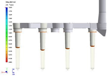 Fig. 1  The unbalanced filling at the sub-runner section
Fig. 1 Â The unbalanced filling at the sub-runner section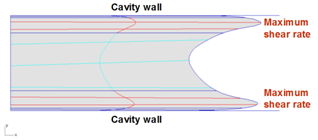 Fig. 2 Â The shear rate profile inside a runner
Fig. 2  The shear rate profile inside a runner Â
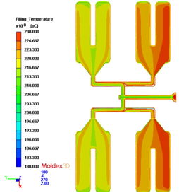 Fig. 3  Cross-section of a runner system showing a symmetrical temperature distribution
in the runner and even inside the cavity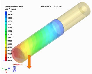 Fig. 4 Â A single cavity with unbalanced flowing showing the deflection of the core insertÂ
Fig. 4  A single cavity with unbalanced flowing showing the deflection of the core insert 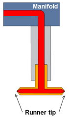 Fig. 5  An example of a side gate hot runner design
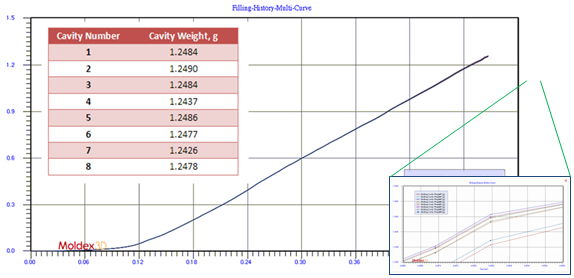 Fig. 6  Predictions of cavity weight with increasing filling percentage at different cavities. Note that the prediction of a slight weight variation is still possible even with the use of a hot runner