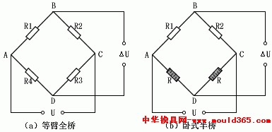
This paper introduces a new method of measuring the cutting force of CNC lathe using AT89C51 single-chip microcomputer, and focuses on the method of continuous automatic sampling, A/D conversion, scale conversion and data processing. The article gives the principle and structure of the single-chip microcomputer measurement and control system and some procedures for data acquisition. 1 Proposed issue In the machining of CNC lathes, the measurement of cutting forces is very important. Through the measurement of cutting force, the stress conditions and working conditions of various parts, mechanisms or structures of CNC lathes can be analyzed and studied. The correctness of the design and calculation results is verified, and the load spectrum and certain physical phenomena in the whole working process are determined. The mechanism. Therefore, he has a very important role and application value in the development of design theory, ensuring the safe and reliable operation of CNC machine tools and the realization of automatic processing, automatic detection, automatic control and cutting force overload alarm of CNC machine tools. 2 system hardware interface circuit design System hardware block diagram shown in Figure 1. The system uses the AT89C51 microcontroller as the control core, and the peripheral circuit is designed for the functional characteristics of the single-chip microcomputer. It fully utilizes the on-chip resource-rich features of the AT89C51 microcontroller, simplifies the peripheral circuit and improves the reliability. In the following, the major functional modules and hardware reliability technologies in the system are analyzed one by one. Figure 1 System hardware block diagram 2.1 Cutting force and force In order to facilitate the measurement and study of CNC lathe cutting force, especially to meet the needs of designing and using CNC machine tools, tools and fixtures in production, the total cutting force Fr is generally decomposed into three mutually perpendicular forces, ie Fz, Fy. , Fx to study. 2.2 Force sensor The most commonly used sensors in dynamometers are resistance wire strain gauges and piezoelectric crystals. The octagonal ring dynamometer we designed is a resistance wire strain gauge dynamometer. The working principle is that the octagonal ring of the dynamometer is an elastic element. The resistance strain gauges are attached to the inner and outer walls of the ring, and are connected into three bridges as a sensor for measuring the cutting force in three directions of X, Y and Z. When the lathe is turned, the turning force is transmitted to the turning tool through the rotation of the workpiece, and is then transmitted to the octagonal ring by the turning tool bar. The deformation of the octagonal ring deforms the resistance strain piece closely attached thereto, and the resistance value R occurs. Change (R±ΔR). When the strain gauge is stretched, the diameter of the resistance wire becomes thinner, and the resistance value increases (R+ΔR). When the strain gauge is compressed and deformed, the diameter of the resistance wire becomes thicker and the resistance value becomes smaller (R-ΔR), thereby outputting Proportional electrical signal. It is known from the experiment that since the resistance change of the resistance strain gauge is very small, it is necessary to amplify the signal to 0-5V before inputting the SCM control system for corresponding processing. The bridge formed by the resistance strain gauges is shown in Figure 2. a) The figure shows an equal-arm full-bridge circuit and b) shows a horizontal half-bridge circuit. Figure 2 The bridge formed by the strain gages In Figure 2, a) bridges R1, R2, R3 and R4 composed of resistance strain gages are the resistances of four bridge legs, respectively. When A and C terminals are connected to a certain bridge voltage U, the output voltage U at terminals B and D is obtained from the following equation: (1) From formula (1), we can see that when R1R3=R2R4, the bridge output voltage ΔU=0, that is, the bridge is in balance, which is the adjustment of the bridge balance that must be performed before the cutting force is measured. Under the action of cutting force, the resistance of the strain gauge changes, destroying the balance of the bridge. If R1, R2, R3, and R4 respectively produce resistance changes of ΔR1, ΔR2, ΔR3, and ΔR4, the output voltage from the bridge of equation (1) is: (2) From the equation (2), it can be seen that an important property of the bridge is that when the resistances of the two adjacent arms of the bridge have the same sign change, the output voltage of the bridge is the result of the decrease of the resistance of the two bridges. Therefore, when the dynamometer is connected to the bridge, in order to make the bridge have a larger output, the resistors in opposite sides of the two arms of the bridge should be changed in resistance, and the two arms have the same sign change. This is the principle of the dynamometer cloth on the bridge. The dynamometer's commonly used bridge has an equal-arm full-bridge (a bridge consists of four arms, R1 = R2 = R3 = R4) and a half-bridge (the bridge consists of two arms plus two fixed resistors, R1 = R2 =R), as shown in Figure 2. The output voltage of the two bridges of type (2) is: Full Bridge: ΔU=U/4R(ΔR1-ΔR2+ΔR3-ΔR4) (3) Half-bridge: ΔU=U/4R(ΔR1-ΔR2) (4) Comparing (3) and (4) shows that when ΔR1 = ΔR3 = +ΔR; ΔR2 = ΔR4 = -ΔR, the output of the full bridge is twice that of the half-bridge, that is, the sensitivity of the full bridge is twice that of the half-bridge. Therefore, in order to improve the sensitivity of the dynamometer, that is, the bridge has a large output, we used the measurement circuit of the equal-arm full bridge when designing the dynamometer. 2.3 Range Amplifier The signal output by the sensor is generally μv-mv level, and is amplified to a uniform level 0-5V that the analog-to-digital converter can receive. 2.4 Multiple Switches The electric signals of each channel transformed by the sensor in the cutting process of the CNC lathe are connected with the A/D to perform A/D conversion, which not only saves equipment, but also does not make each measured parameter compete with each other. The number of the channel each time the multiplexer is closed is controlled by the program. 2.5 sample and hold circuit Since the cutting force measured at the site is continuously changing, while the sampling of the single-chip microcomputer is intermittent, in order to maintain the original value when the parameters are not sampled, a sample-and-hold circuit needs to be added. We have adopted large-scale integrated circuits. Chip LF398. 2.6 A/D Converter The analog voltage output from the load cell becomes a digital quantity. We chose the ADC0809 eight-bit A/D converter. His conversion method is the successive approximation method. Inside the A/D converter there is a high-impedance chopper-stabilization comparator, a 256R divider with an analog switch array, and a progressive-approximation register. The eight analog switches can be controlled by the address locker and decoder and can access any one of the unilateral analog signals in eight paths. 2.7 Display cutting force Although the A/D converter converts the analog voltage output from the load cell to a digital value, it is not the value of the actual CNC lathe cutting force. To obtain the true value of the cutting force, the following two steps are required: Static calibration And scale transformations. Static calibration: It is through the experiment to establish the relationship between the output voltage of the load cell and the cutting force and mathematical model. Scale conversion: It is the value of 00H-FFH digital converted by the A/D converter to the actual cutting force value. After the above two steps are completed, the actual cutting force value of the CNC lathe can be displayed on the SCM LED. For CNC lathe operators to monitor and manage production. 3 System Software Design The main program block diagram of the system is shown in Fig. 3. The system software includes: dynamic display program, A/D sampling program, scale conversion program and interrupt service program. 3.1 A/D sampling procedure Figure 3 system main program block diagram Figure 4 scale conversion subroutine block diagram Some of the reference procedures are as follows: Main program: ORG 0A00H Interrupt service program: 3.2 Scale Subroutine Block Diagram From the experimental results, it is known that the digital quantity converted by the A/D system has a linear relationship with the value of the cutting force of the CNC lathe. Therefore, the mathematical formula for the scale transformation is: Ax=A0+(Am-A0)(Nx-No)/(Nm-No) In order to make the program simple, the A/D conversion value corresponding to the starting point A0 (the input signal is 0) of the measured parameter is generally 0, that is, N0 = 0, so the formula becomes: Ax= Nx/Nm(Am-A0)+A0 The system scale conversion subroutine block diagram shown in Figure 4. 4 Conclusion The single-chip microcomputer was used to measure the cutting force of the CNC lathe and realized continuous automatic sampling, real-time display and overload alarm in the production process, so that the operators could monitor and manage the production, effectively preventing the occurrence of damage to the CNC lathe due to excessive cutting amount. This system can also be improved and transplanted to other fields that need to be limited.
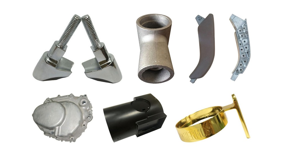
In the past, the use of magnesium alloy die castings was relatively small, and now it is slowly increasing. Because magnesium alloys have the characteristics of low density and strong rigidity, many parts of shells and brackets use magnesium die castings. For example, the fast-developing mobile phones and notebook computers in recent years often use magnesium die casting for the support frame and the back shell. However, compared with aluminum alloy die casting and zinc alloy die casting, the cost of magnesium alloy die-casting will be relatively high.
The melting point of magnesium alloy is relatively low, and it needs effective gas protection during die casting, which is easy to oxidize and burn. Therefore, the professionalism of die casting is relatively strong, and the requirements for die casting personnel are generally relatively high. SCZY has professional and technical personnel for die-casting magnesium alloy products to ensure the quality of the products. Including one-stop services such as precision CNC machining and surface treatment provided later.
Magnesium Die Casting,Magnesium Alloy Die-Cast,Magnesium Alloy Die Casting In Automobile,Magnesium Alloy Die Casting Processing,Magnesium Die Casting Parts Shenzhen SCZY Technology Co.,Ltd , https://www.szsccasting.com

The interrupt service routine mainly uses the time scale generated by the timer interrupt to dynamically refresh and display the LED digital tube.
This program divides the main program and interrupt service program in two parts. The main program is used to initialize the interrupts, send a start pulse to the ADC0809, send an analog number of addresses, dynamic display, monitoring alarms. The interrupt service routine is used to receive the A/D converted digital quantity and determine whether the sampling is completed once or not. 

MOV R1, #30H; Input data area start address MOV R4, #03H; Analog total path number send R4
MOV R2, #00H; IN0 address send R2
SETB EA
SETB EX0
SETB IT0
MOV R0, #0F0H
MOV A, R2
MOVX @R0,A
SJMP $ ; wait for interrupt
ORG 0003H
AJMP CINT1
ORG 0100H
CINT1: MOV R0, #0F0H
MOVX A, @R0
MOV @R1,A
INC R1
INC R2
MOV A, R2
MOVX @R0,A
DJNZ R4, LOOP; if no 3 roads have been collected, turn LOOP
CLR EX0; If 3 channels are acquired, the INT0 interrupt LOOP is turned off: RETI
END
A0 ─ The lower limit of a measuring instrument Am ─ ─ The upper limit of the measuring instrument Ax ─ Actual measured value N0 ─ The digital quantity corresponding to the lower limit of the meter Nm ─ The digital quantity Nx corresponding to the upper limit of the instrument ─ Corresponding to the measured value Digital quantity 